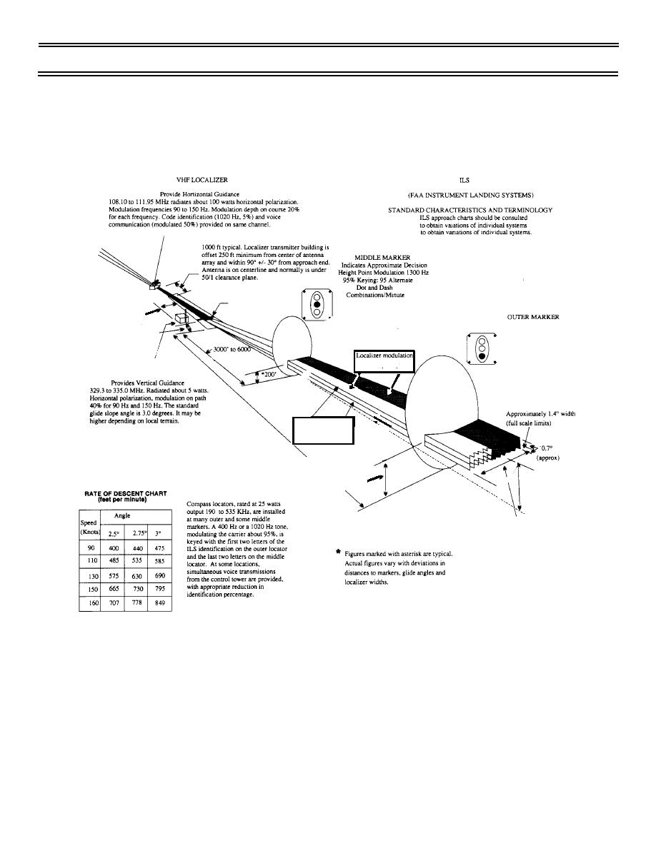

These lateral cues correspond to the centreline of the runway being approached. As mentioned above, there is only a horizontal or lateral component present in this form of approach. LOC ApproachĪ LOC approach can be defined as a non-precision approach, in which there is no vertical guidance or descent profile provided to the runway. An ILS approach consists of both the lateral (localizer) and vertical (glideslope) components. The difference between an ILS and LOC approach is that a LOC consists only of lateral/horizontal guidance to the runway centreline. Two forms of instrument approaches are an ILS – short for Instrument Landing System, and LOC – which stands for the localizer. This video shows the Instrument Landing System in operation.Under Instrument Flight Rules (IFR), there are a number of different instrument approaches which may be performed, depending on the airport’s infrastructure and the aircraft’s capabilities. When the airplane passes through outer marker, the blue lamp blinks emitting a 400 Hz sound, passing through the middle, the orange blinks with a 1300 Hz sound and when passes through inner marker, the white blinks with a 3000 Hz sound. In cabin, there are three lamps which indicate when the airplane passed through a marker beacon.

The pilot must keep the white lines in the dotted lines. This is the course and deviation indicator, serves to show the pilot if he is aligned with localizer and glideslope’s axes. The receivers to localizer and glideslope stay in the airplane’s nose and the marker beacon receiver stays below, close to the front wheel. Each marker transmit a sound in different frequency to aircraft. When the aircraft pass through a marker, it emits a sound inside the airplane cabin. Usually, are 3 transmitters of 75 MHz with 2 W power. Inform how close the airplane is from the runway. I already explained in the post about LCD, how light polarization works, since radio waves are electromagnetic waves like the light. The right angle is when the aircraft receives both the 90 and 150 Hz signals.

The glideslope guides the airplane to neither stays too high, neither too low. Are modulated to transmit in UHF frequency between 329.30 and 335 MHz. Sends two radio signals vertically polarized, in frequencies 90 and 150 Hz. It is an array of antennas vertically positioned. The airplane knows it is aligned when receives two signals of frequencies 90 and 150 Hz at the same time. The localizer guides the aircraft to stay aligned with the runway’s center. These signals are modulated to be transmitted in VHF with frequencies between 108 and 111.975 MHz. The antennas transmit two radio signals in frequencies 90 and 150 Hz, horizontally polarized. It is an array of antennas in the runway’s end, positioned horizontally. The components of Instrument Landing System are: localizer, glideslope and markers beacon. When there is low visibility, the airplane is guided by radio waves to land in the right angle and be lined up with the runway. How is it possible? Enter the Instrument Landing System (ILS), meeting requests, it is this post’s subject. Many airplanes can land with low visibility caused by fog.


 0 kommentar(er)
